MIL-DTL-19379C(SH)
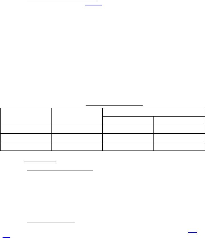
4.4.2.1.2 Method for measuring dynamic stiffness. Dynamic stiffness shall be measured for each mount in the
axial direction at the test conditions specified in table XIII to determine conformance with 3.5.2. The measurement
method is based on the transmitted force principle and is used to define the properties of a dynamic model consisting
of a parallel combination of an ideal spring and damper to represent the mount. Although a more exact model
includes a mass term, it may be omitted with negligible error at low excitation frequencies. Dynamic stiffness
measurements, as defined in this specification, shall be acquired by following the guidelines given in ASTM D5992
for forced non-resonant measurements using the Fast Fourier Transform (FFT) method. This requires measurement
of the sinusoidal displacement amplitude (X) at the input of the mount and transmitted dynamic force amplitude (F)
at the blocked output of the mount, as well as the phase relationship (θ) between them. The dynamic stiffness is
calculated from the measurements as follows:
K = C(F/X)(cos(θ + δ))
Where "C" and "δ" are minor adjustment factors, if necessary, to account for test apparatus flexibility and
instrumentation phase shift (see 4.4.2.1.1).
The measured stiffness may require adjustment to account for test apparatus flexibility and instrumentation
phase shift (see 4.4.2.1.1). The mount shall be "conditioned" by cycling it three times from "0" to its upper rated
load (15 pounds for 11M15, 25 pounds for 11M25, and 50 pounds for 10M50) prior to the start of measuring
dynamic stiffness. Then, at each static load condition, the mount shall be vibrated and allowed to settle before
readjusting (if necessary) to the required load before acquiring dynamic stiffness data.
TABLE XIII. Dynamic stiffness test conditions.
Excitation
Mount type
Axial static load (lbs)
(inches, pk-pk)
(Hz)
11M15
9, 12, 15
0.01
11
11M25
15, 18, 22, 25
0.01
11
10M50
25, 33, 42, 50
0.01
10
4.4.2.2 Static strength test.
4.4.2.2.1 Apparatus for conducting strength test. A suitable test system capable of loading the mounts at a
constant rate of deflection while measuring load and deflection shall be used. A commonly used type of equipment
for measuring load-deflection is a Universal Testing Machine. The sampling rate of measured load and deflection
shall provide a sufficient number of samples to furnish smooth load-deflection plots without discontinuities.
Deflection shall be measured to the nearest 0.001 inch. Flexibility of the test system (load frame, force gauge,
fixtures, etc.) shall be accounted for via correction of measured mount data. A test system which is at least 100
times stiffer than the static stiffness of the mounts being tested shall not require a flexibility correction. To avoid
over-correction, the stiffness of the test system shall be at least 30 times greater than the stiffness of the mounts
being tested. All sensors used for measurement (force and displacement transducer) shall be calibrated at regular
intervals.
4.4.2.2.2 Axial direction strength test. A single mount shall be secured in a test fixture and subjected to four
loading and unloading cycles at a constant deflection rate not to exceed 0.3 inch per minute. The peak load obtained
shall be to "Level A" for the first three loading cycles and to "Level B" for the fourth loading cycle (refer to table
XIV). Load-deflection data shall be recorded during the fourth loading cycle. The mount shall be inspected during
and after testing to determine compliance with 3.5.3
12
For Parts Inquires call Parts Hangar, Inc (727) 493-0744
© Copyright 2015 Integrated Publishing, Inc.
A Service Disabled Veteran Owned Small Business